Project Background
The survey consists of an AutoCAD drawing containing 3D polylines (pipe inverts) and blocks and text for manholes and data. Features such as kerbs, roads, banks etc are also included so a ground model can be generated.
This is the aerial image of the area with the site outlined in red.

The survey drawing for the underground utilities will usually be 'crowded' - see below:

Initial Drawing Setup
Generally the best first step is to copy and paste everything from your survey drawing into your C3D template - in my case I am using the AutoCAD Civil 3D UKIE.dwt.
Create your ground model from the survey drawing - see the following post if you are creating from CAD elements.
Isolate only the objects you need - so in this case I need anything to do with the storm network - pipes, manholes, text, gullies etc. Also isolate objects that affect the flow of water on the ground (kerb lines, buidlings etc) so we can determine catchments for the network. The drawing will be a lot simpler to read.

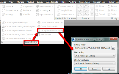
Set Pipe & Structure Catalog
Next set the pipe and structure catalog to your localised settings. The catalogs are the highest level library of pipes and structures and contain all the elements that you can use in the drawing.

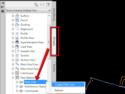
Create a Parts List
Next create a Parts List - this is a subset of the higher level catalog and will generally contain only the pipes and structures required for a particular type of network - eg Storm, Foul, Electrical ducting, water network etc. To create a parts list go to the Settings Tab of Toolspace and expand the Pipe Networks section. Right Click on Parts Lists and select Create Parts List. Give you Parts List a name.

Add Part Families & Sizes
The new parts list will initially be empty. We need to add in the pipe and structure types and sizes for our network. Still in the Create Parts List dialog box, browse to the Pipes tab. Right click on your network name and select 'add part family'.
 Once added then right click on the family and choose 'add part size' Tick the sizes you need or the box to add all sizes.
 Repeat these steps on the structures tab for the types and sizes you require.
Assign Rules & Styles
Apart from creating a smaller more manageable set of pipes and structures the other main use of the parts list is to assign styles (for plan, profile, section) and rules to your pipes.


Assign Rules & Styles
Apart from creating a smaller more manageable set of pipes and structures the other main use of the parts list is to assign styles (for plan, profile, section) and rules to your pipes.
The rules are more useful when laying out a proposed network and for this type of work we do not want to apply any rules. You can't turn rules off but you can create your own set of 'empty' rules. Still in the same dialog box click on the button to assign Rules and then create a new rule set. Do not add any rules and call the set something like _NO RULES.

For the styles select one that is appropriate for your needs. I like the Solid Centreline Schematic from the UKIE template. Follow similar steps for the structures, apply a NO RULES set and an appropriate style.
The next post covers drafting of the pipe network...
No comments:
Post a Comment